
A number of years ago, I created wifi-enabled touch lights to help my family keep in “touch” with each other. Recently though, my father-in-law and his mom were having trouble with the lights’ capacitive touch sensing. One issue they experienced was that the capacitive touch sensing would fail to respond to their touch after a number of weeks of being plugged in. Additionally, they experienced issues with the circuits getting zapped from static electricity, which would damage the Particle Photon boards.
In an effort to remedy these problems, we modified their touch lights to incorporate a pushbutton switch for triggering the touch light. Below are details for how to replace the capacitive touch-sensing functionality of your wifi touch light with a pushbutton switch.
Hardware Changes
From a hardware perspective, creating the pushbutton wifi touch light is very similar to the capacitive touch sensing touch light. Follow the same instructions to build the capacitive touch sensing touch light, but instead of attaching the 10M-Ohm resistor and touch plate wire to pins D3 and D4, attach each end of the switch to D3 and D4 respectively (it does not matter which wire is connected to which pin).
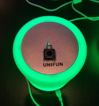
The switch can be be mounted anywhere on the light. In our case, we drilled a hole through the center of the touch plate. We mounted the switches using a hot glue gun. The hole drilled through the center of the white dome also needs to be larger to account for two wires passing through it. You can use any pushbutton switch that is closed when pressed and open when released (a push lock switch will not work). In our case we used a reset button from an old computer.
Software Changes
At a high level, the code that detects a touch event will need to be replaced with code that detects a button push event. The touch event code works by setting the set pin to HIGH, and then continuously reading the read pin to measure the time it takes to propagate the HIGH signal. It finds a baseline for this reading and detects when a new measure falls far from this baseline (which happens when a conductive field enters the vicinity of the touch plate). The switch code is considerably simpler. It can write a HIGH to the set pin at setup and then detect when the read pin goes from LOW to HIGH or HIGH to LOW.
In the setup function we can remove the interrupt attached to our read pin and replace it with the proper setup for our read and write pins.
void setup() {
  // More stuff here

  pinMode(sPin, OUTPUT);
- attachInterrupt(rPin, touchSense, RISING);
+ pinMode(rPin, INPUT);
+ digitalWrite(sPin, HIGH);

  // More stuff here
}
The new setup sets the rPin to INPUT mode so it is set up for reading, and sets the sPin to HIGH.
Once the pins are properly set up, we need to replace the function that detects touch events with a new function that detects button presses. The function that detects touch events happens at the very top of the main loop function.
void loop() {
  int touchEvent = touchEventCheck();

  // More stuff here
}
This function needs to be replaced with a new function that maintains the same interface. The touchEventCheck detects touches and returns whether the light was touched, released, or there was no change.
//------------------------------------------------------------
// touch event check
//
// check touch sensor for events:
//      tEVENT_NONE     no change
//      tEVENT_TOUCH    sensor is touched (Low to High)
//      tEVENT_RELEASE  sensor is released (High to Low)
//
//------------------------------------------------------------
int touchEventCheck() { }
We will replace this function with a new function switchEventCheck that detects button pushes and returns whether the button was pushed or released.
//------------------------------------------------------------
// switch event check
//
// check manual switch for events:
//      tEVENT_NONE     no change
//      tEVENT_TOUCH    sensor is touched (Low to High)
//      tEVENT_RELEASE  sensor is released (High to Low)
//
//------------------------------------------------------------
int switchEventCheck() {
  int touchSense;             // current reading

  static int touchNow = LOW;  // current debounced state
  static int touchLast = LOW; // last debounced state

  int tEvent = tEVENT_NONE;   // default event

  if (digitalRead(rPin) == HIGH) {
    touchSense = HIGH;
  } else {
    touchSense = LOW;
  }

  touchNow = touchSense;

  // set events based on transitions between readings
  if (!touchLast && touchNow) {
    tEvent = tEVENT_TOUCH;
  }

  if (touchLast && !touchNow) {
    tEvent = tEVENT_RELEASE;
  }

  // update last reading
  touchLast = touchNow;
  return tEvent;
}
void loop() {
  int touchEvent = switchEventCheck();

  // More stuff here
}
The last change that needs to be made is to ensure our touch light updates its color within the main loop. This behavior used to happen in touchEventCheck. The reason for this is that executing the color-update code only once per main-loop iteration would not execute fast enough for a gradual color transition. We will place the color update code in the main loop because our switchEventCheck code executes a lot more quickly.
void loop() {
  static int loop_number = 0;

  if (!(loop_number % SAMPLES_BETWEEN_PIXEL_UPDATES)) {
    updateState();
  }

  loop_number++;

  int touchEvent = switchEventCheck();

  // More stuff here
}
We kept the code that updates the touch light’s color only once every 32 iterations of the main loop. This makes for a very gradual transition between colors. If you want a quicker transition, you can reduce the value of SAMPLES_BETWEEN_PIXEL_UPDATES
Final Result
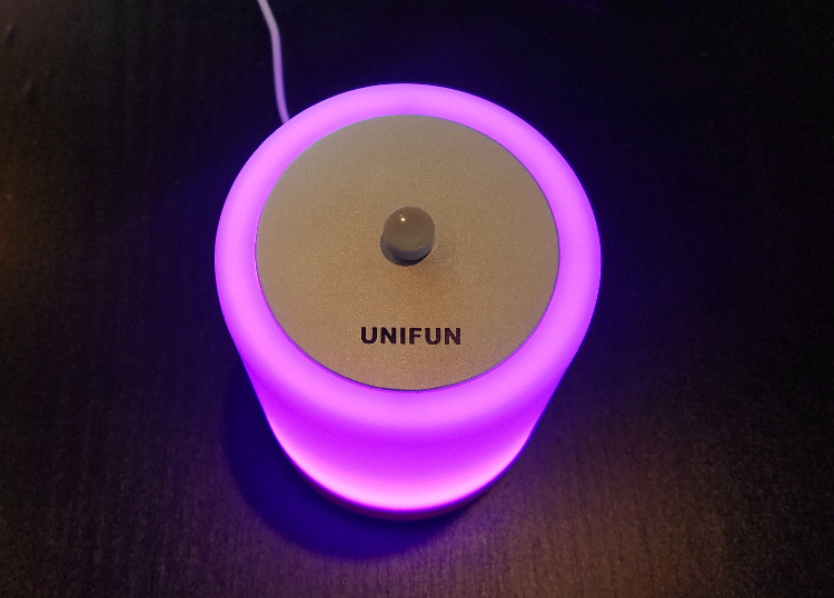
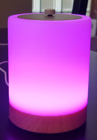
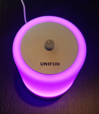
After making these hardware changes and adding the above code, you can have a pushbutton-triggered wifi touch light.
Cheers!